1. EXTERNAL DEVICES
Can be classifies into three categories:
a. Human Readable
- Suitable for communicating with the computer user
- Example are video display terminals (VDT) and printers
b. Machine Readable
- Suitable for communicating with equipment
- Example are magnetic disk and type system,sensor and actuators
c. Communication
- Suitable for communicating with remote devices
- Allow a computer to exchange data with a remote device
- Keyboard
- Mouse
- Scanner
- CD-Rom
- Game Controller
Keyboard / Monitor
- Most common means of computer / user interaction
- Keyboard provides input that is transmitted to the computer
- Monitor displays data provided by the computer
- The character is the basic unit of exchange
- Each character is associated with a 7 or 8 bit code
OUTPUT DEVICES
- Monitor
- Printer
- Disk Drive
- Floppy Drive
- CDRW-Rom
- Speakers
Disk
Drive
- Contains electronics for exchanging data, control, and status signals with an I/O
- Contains electronics for controlling the disk read/write mechanism
- Fixed-head disk – transducer converts between magnetic patterns on the disk surface and bits in the buffer
- Moving-head disk – must move the disk arm rapidly across the surface
3. INPUT OUTPUT MODULE
Purpose of Input Output Module
- Interface to the processor and memory via the system bus or control switch
- Interface to one or more peripheral devices
Input Output Function
- Control & Timing
- CPU Communication
- Device Communication
- Data Buffering
- Error Detection
Control & Timing
- Processor checks input output modules for external device status
- Input output returns status
- If device ready, processor gives input output module command to request data transfer
- Input output module gets a unit of data from device
- Data transferred from the input output module to the processor
Processor Communication
Involve the following:
Command decoding - input output modules accepts command from the processor sent as signals on the control bus
Data - data exchanged between the processor and input output module over the data bus
Status reporting - common status signals BUSY and READY are used because peripherals are slow
Address recognition - input output must recognize a unique address for each peripherals that it control
Input Output Module Communication
- Device communication - commands, status information, and data
- Data buffering - data comes from main memory in rapid burst and must be buffered and the sent to the device's rate
- Error detection - responsible for reporting error to the processor
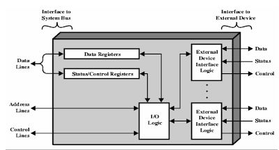
Input Output Module Structure
• Module connects
to the computer through a set of signal lines – system bus
• Data transferred
to and from the module are buffered with data registers
• Status provided
through status registers – may also act as control registers
• Module logic
interacts with processor via a set of control signal lines
• Processor uses
control signal lines to issue commands to the I/O module
• Module must
recognize and generate addresses for devices it controls
• Module contains
logic for device interfaces to the devices it controls
• I/O module
functions allow the processor to view devices is a simple-minded way
• I/O module may
hide device details from the processor so the processor only functions in terms
of simple read and write operations – timing, formats
• I/O module may
leave much of the work of controlling a device visible to the processor –
rewind a tape
to be continued...
nadhiah amira nordin
<B031310415>


No comments:
Post a Comment